Gigabyte Ultra Durable Make Load Optimized Defaults Option
First up Long time, no see. It’s been a while since my last review, but hopefully I’ll be a more frequent sight on the frontpage in the foreseeable future. Anyways, on the the good stuff. Today we have the Z170X-UD5 which is in the upper tier of GIGABYTE’s current lineup, just behind their. Being near the top of the lineup, the UD5 looks like a great board on paper and deserves a good testing. Z170 (Sunrise Point) ChipsetOn to the expansion slot layout. There are three PCIe 3.0 x16 slots running at x16/x8/x4, four PCIe 3.0 x1 slots, and two M.2 slots.
The top two PCIe x16 slots share bandwidth, so their configuration becomes x8/x8 when both are being used. Also, the bottom PCIe x16 slot shares bandwidth with the lower M.2 slot (M2H32G), so only one of those can be used at a time. The other M.2 slot shares bandwidth with some of the SATA ports, which we’ll go into more specifically later. I personally like the PCIe slot layout, particularly having a PCIe x1 slot at the top and two slots between the top two PCIe x16 slots. The top PCIe x1 allows for good clearance between a large CPU cooler and the first PCIe x16 slot (typically a GPU).
Having two slots between PCIe x16 slots allows having a whole slot’s worth of space between two dual-slot GPUs in SLI or CFX for better cooling due to a less blocked air intake on the top card. PCIe ShieldingThe most prominent feature at the top right corner of the board are the four DDR4 DIMM slots. The 24-pin motherboard power header is located here, alongside a SATA power header which supplies auxiliary power to the PCIe x16 slots. We have two 19-pin USB3.0 headers between the DIMM slots and 24-pin power header to add up to four additional USB3.0 ports. Two CPU fan headers are available between the DIMM slots and VRM heatsink for push/pull fan configurations on the CPU heatsink.

Gigabyte Ultra Durable Make Load Optimized Defaults Option Windows 10
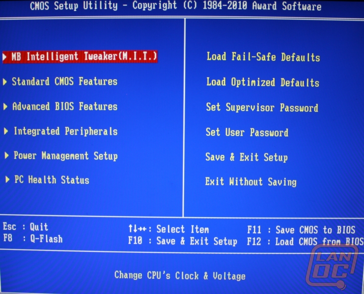
There are quite a few buttons on this part of the board as well: red Power, white Reset, black CMOS reset, “OC” automatic overclocking, and “ECO” power savings. In my opinion, the most interesting feature located in this area of the board are the voltage read points above the DIMM slots so you don’t have to rely on software for voltage readings. Internal I/OThe SATA configuration is two ASMedia SATAIII ports on the top right stack powered by an ASM1061 chip, the other six SATAIII ports on the Z170 chipset, and three SATA Express connections using the aforementioned six Intel SATAIII ports. When a M.2 SSD is being used in the top M.2 slot (M2D32G), one or more SATA ports will become unavailable for use depending on controller mode (AHCI or RAID) and whether the SSD is SATA, PCIe x2, or PCIe x4. In AHCI mode for example, when using a SATA M.2 SSD, SATA port 3 is disabled; when using a PCIe x2 M.2 SSD, SATA ports 2 and 3 are disabled; when using a PCIe x4 M.2 SSD, SATA ports 0, 1, 2, and 3 are disabled. More details can be found on page 30 of the User Manual. SATA Ports UEFI BIOSThe first tab, M.I.T., is where most of your time will be spent when tweaking BIOS settings.
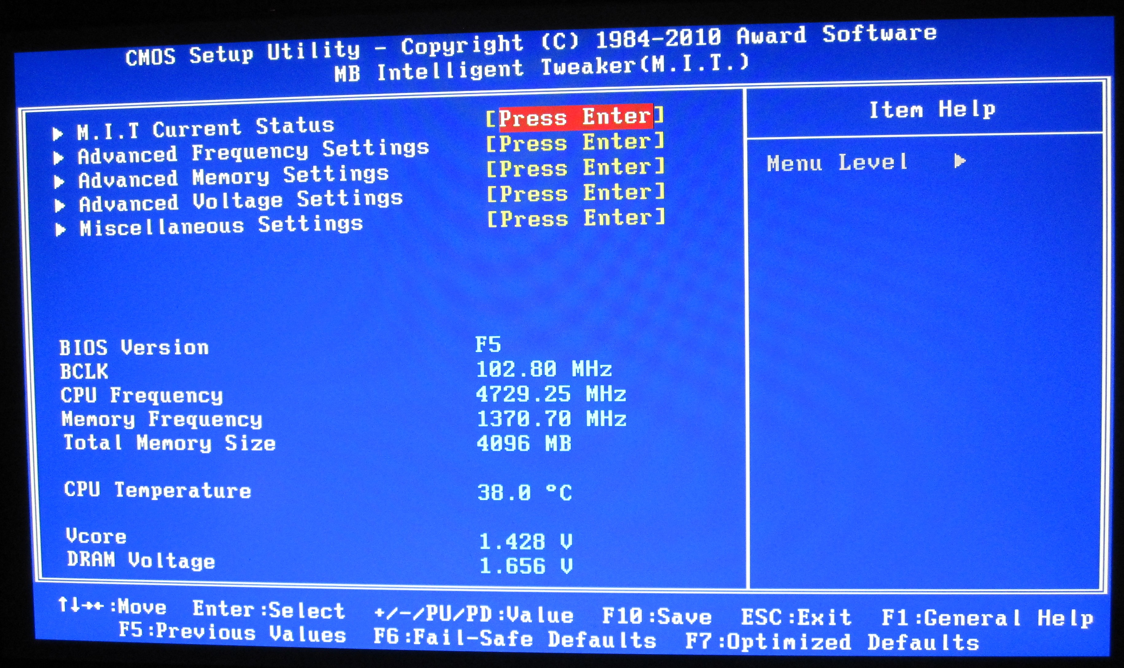
The Advanced Frequency and Advanced Memory sections are where all the multipliers, bclk, and timings are located for the CPU and RAM. The Advanced Voltage section is, as you could have guessed, where all the CPU, iGPU, RAM, Chipset, etc. Voltages are located along with load line calibration settings for the CPU Core and iGPU. I’m a fan of the Current Status and PC Health sections to get an overall look at your current frequencies, timings, multipliers, and voltages. It’s worth noting that PC Health shows motherboard voltage readings, not your voltage settings.

For instance, in these screenshots, my Vcore is set to 1.3 V, but shows as 1.272 V in the PC Health screen.This slideshow requires JavaScript. SoftwareEasyTune is GIGABYTE’s overclocking software which is great for basic overclocking via multipliers and voltages. The Advanced CPU OC tab is where we can change the bclk, multipliers on a per core basis, system voltages, and save/load OC profiles.
The Advanced DRAM OC tab just allows RAM multiplier adjustment and enabling/disabling XMP. This tab does show the RAM timings, but they aren’t adjustable.
The Advanced Power tab lets us change the load line calibration setting. In the Hotkey tab we can assign OC profiles to hotkeys so they can be changed on the fly. I also included screenshots of both the light and dark themes, and the highlight color (bright blue) can also be changed to customize the look even further.This slideshow requires JavaScript.
Test SetupThis is a brand new platform for me, so this will be my first experience overclocking and tweaking Skylake. Test SetupCPU@ 4.2 GHz, 1.3 VCPU CoolerNoctua NH-D14MotherboardGigabyte GA-Z170X-UD5RAM2×8 GB Patriot Viper 4 DDR4-3000 15-15-15-35, 1.35VGraphics CardIntel® HD Graphics 530Hard DriveWestern Digital Black 640 GBPower SupplySeaSonic Platinum-1000Operating SystemWindows 7 Pro x64 SP1BenchmarksAIDA64 Engineer (v5.50.3600)Cinebench R15x264 HD Benchmark (v5.0.1)POV Ray (v3.7)Intel XTU (v6.0.2.2)MaxxMEM 2 (v2.01)SuperPiwPrimeEquipmentFluke 115 Digital MultimeterLoad Line CalibrationLoad line calibration or LLC controls the fluctuation of Vcore between idle and load states. Typically, there is a drop in Vcore as a CPU is loaded called Vdroop. So, if the CPU is stable at a certain Vcore, but then drops below that Vcore while loaded, the CPU could become unstable.
To counter this effect we either have to offset the Vcore to a higher value while idle so it doesn’t drop too far when loaded, or we can use LLC to keep the Vcore from dropping too low when the CPU is loaded.There are two LLC settings on the Z170X-UD5, Standard and High. So, I set the Vcore to 1.3 V in the BIOS, then I used a multimeter to measure the voltage directly off of the board’s read points near the DIMM slots. I did this both for idle Vcore and loaded Vcore while running LinX 0.6.5 in Windows.
The idle measurement shows the Vcore drop between what was set in the BIOS and when the CPU is under the very light load of the Operating System. When using Standard, the Vcore is 0.025 V less when idle and 0.079 V less when loaded than the target Vcore. The High setting does a much better job at stabilizing the Vcore to what you want since it only drops by 0.004 V when idle and 0.005 V when loaded.CPU OverclockingOverclocking Skylake wasn’t really any different than previous Core series Intel processors. The only settings that need to be adjusted are the CPU multiplier and Vcore. Although, with Skylake, we do have much more bclk control and I did boot with 150 MHz bclk, but it was much more of a hassle dealing with it since adjusting it requires multiple hard resets.
So, for an everyday overclock, I’d just forget about the bclk and leave it at 100 MHz. However, for benching, I’d return to the bclk for fine tuning and trying to squeeze every last bit out of the CPU/RAM.I started my overclocking by setting the Vcore to 1.4 V and the multiplier to 46, but that resulted in the CPU reaching its TJmax of 100 °C when running LinX. So, I dropped the Vcore down to 1.35 V and that worked for 4.6 GHz and keeping temps under the TJmax. Next, I increased the multiplier to 47, but the voltage wasn’t high enough to complete an10 minute LinX run. So, I started increasing the voltage in small increments up to 1.375 V with testing between, and that’s when I was able to pass the LinX run. Since temps were already in the mid-high 96-97 °C on a couple cores, I stopped there knowing I’d be temperature limited if I went any further.
I was using a NH-D14 with an ambient temperature of 26 °C when getting this overclock. I think some more could be gained with better cooling, such as good water cooling (not cheap AIO units). X264 @ 4.7 GHzConclusionGIGABYTE’s GA-Z170X-UD5 is a great looking board with plenty of features for the enthusiast. My personal favorites include: onboard POST display, onboard power/reset/CMOS switches, voltage read points, PCIe slot reinforcement, and M.2 slots. The UEFI BIOS is also straightforward and easy to use with all the necessary settings for an overclocking board. GIGABYTE’s EasyTune software is good for basic overclocking with multipliers and voltages, which can help you test overclocks before manually setting them in the BIOS. Speaking of overclocking, getting an i7 6700K to 4.7 GHz on air was a breeze, taking all of maybe 15 minutes.
The board also handled overclocking my RAM from DDR4-2800 16-18-18-36 to DDR4-3000 15-15-15-35 for our testing without any problems.The majority of Z170 boards are going between $100-300 with a few outliers at $400-500. The GA-Z170X-UD5 is currently going for which lands in the middle of the pack, which seems fair especially considering all the features packed into the board.Overall, the GA-Z170X-UD5 is a good all-around board with features for everyone. Without any cons or quibbles popping up in my time with the board, I have to say it makes the Approved stamp an easy decision.